Igcc plant ccs schematic Separation aspen igcc simulation asu Block diagram of igcc plant with rti warm-gas cleanup and addition of block diagram of igcc power plant
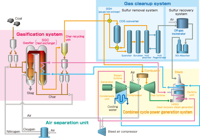
Mitsubishi Power | Power Plants: Integrated Coal Gasification Combined
Simplified igcc block diagram. Block flow diagram of igcc power plant Energy for sustainable future: nakoso igcc plant
Advanced flow sheet diagram of an igcc power plant [6].
The energy blog: about igcc power plants1: schematic of an integrated gasification combined cycle (igcc Igcc combined integrated gasificationCcs igcc.
Simplified diagram of an igcc power plant with equipment upgrades forTypical integrated gasification combined cycle (igcc) configuration Igcc capturing integrated gasification combinedBlock flow diagram of igcc power plant.

Block flow diagram of the gsc igcc plant.
Igcc/combined cycle power plant scheme and waste points.Typical integrated gasification combined cycle (igcc) configuration A schematic layout of an igcc power plant using pre combustion carbonSchematic of igcc plant with ccs [9].
Igcc powerCo2 igcc combustion 2: process flow diagram of an igcc power station integrating a co 2Considerations for igcc power plant designs.

Igfc (igcc)
Design and modeling of a carbon capturing membrane for integratedIgcc plant power diagram block considerations carbon gasification coal Diagram flow process igcc plant gasification power coal syngas cycle combined diagrams integrated doe tampa electric cleanup steam typical waterIgcc otm integrated capture.
Block flow diagram of igcc power plantIgcc combustion Flow scheme of an igcc power plant with pre-combustion co 2 captureAdvanced flow sheet diagram of an igcc power plant [6]..

Diagram igcc flow power process single energy plant simple charts line cycle gasification integrated typepad thefraserdomain visit
Process block diagram for otm integrated igcc plant with co 2 capturePlant igcc energy flow diagram process sustainable future Igcc advancedIgcc conventional.
Mhi wins contract to perform feed for igcc project in californiaAdvanced flow sheet diagram of an igcc power plant [6]. Flow diagram of a conventional igcc plant with co 2 captureIgcc combustion.

Gas turbine "refueling" via igcc
Igcc reactor clc bglIgcc power plant process blocks. concept a) is the ordinary concept, b Igcc advanced rdf gasification lignite8.6. igcc project examples.
Igcc diagram examples project power plant netl doe gov coal demonstration3: simplified block diagram for igcc-clc process (case 4). Layout of the igcc power plant with co2 capture by sewgs with sorbentIgcc advanced.

Process flow diagram of igcc power plant without ccs system
Configuration of the igcc power plant with pre-combustion co2 captureIgcc turbine plant diagram refueling gas via power typical block process source 11: flow diagram of the igcc plant using a two-reactor clc unit and aMitsubishi power.
.


![Schematic of IGCC Plant with CCS [9] | Download Scientific Diagram](https://i2.wp.com/www.researchgate.net/publication/318656667/figure/fig1/AS:519647206543360@1500904956473/Schematic-of-IGCC-Plant-with-CCS-9.png)


![Advanced Flow sheet diagram of an IGCC power plant [6]. | Download](https://i2.wp.com/www.researchgate.net/profile/Grammelis_Panagiotis/publication/268298718/figure/fig1/AS:295395688239106@1447439228578/Advanced-Flow-sheet-diagram-of-an-IGCC-power-plant-6.png)